How to Use a 555 Timer: Easy Breadboard Circuit Guide for Beginners
Breaboard
Circuit
The 555 timer is an essential part when designing your timing circuits. The 555 timer is a beginner-friendly component used in both simple and complex circuits. Its low cost and reliability make it a favorite for beginners and pros alike. Whether you're building an LED flasher, sound generator, or timing delay, the 555 timer can handle it with just a few components. In this guide for beginners, we will walk through how to use the 555 timer. If you aren't familiar with resistors or capacitors, I would recommend checking out our article about the basics of making electronic circuits on your own.
555 Timer Pinout Explained (With Datasheet Details)
Using the 555 timer's datasheet, let's explore the functions of all the pins on the IC. This is what the pinout looks like, taken directly from its datasheet:
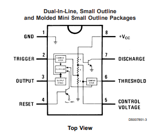
Starting with pin 1:
- Ground (pin 1). This is indicated by a dot or notch at the top of the IC.
- Pin 2 is the trigger. Whenever the trigger goes below a third of the voltage present at VCC, the timer is triggered. This simply means the output (pin 3) is inverted.
- This pin is often connected to a push button in bistable and monostable modes, which are explained later.
- Pin 3 is the output pin. We will be hooking the LED to this pin.
- Pin 4 is the reset. When this pin is pulled low, the timer's output is forced to go low as well.
- Used in circuits where you want to stop the clock and debug
- Can be used in all modes
- Pin 5 is the control voltage pin. We won't be looking at this pin. What you need to know, though, is that we will be connecting a .01 µF capacitor to avoid unwanted noise that can cause our circuit to not work.
- Pin 6 is the threshold pin. When the voltage present on this pin is 2/3 of the Vcc's voltage, then it turns the output low.
- Used in all modes
- Pin 7 is the discharge. This is often connected through a polar capacitor to ground. The capacitor charges and discharges, which when in astable or monostable modes, causes the output to toggle from high to low like a clock.
- Pin 8 is the VCC, or input voltage.
The uses of a 555 timer in electronics all branch off of these pins. Understanding them is crucial in understanding what a 555 timer does and how a 555 timer works.
555 Timer Voltage Requirements and Current Limits
According to the 555 timer's datasheet, the minimum input voltage is 4.5 and the maximum is 16. The 555 timer offers its use in a very broad range of circuits. The 555 timer, however, cannot handle a lot of current.
- For 5V, the max is 6 mA
- For 15V, the max is 15 mA
If you need a high current output, it is best to run the output through an amplifier.
How to Read a 555 Timer Timing Diagram
Something that will help in this tutorial is understanding timing diagrams. This timing diagram is what the bistable mode of the 555 timer looks like:
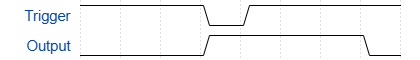
There are a few things to notice. When the line is lower, that means that specific line is at its low logic level state. At the beginning, they all start low. When “Trigger” goes high, then “Output” goes high, indicated by the line being higher than it was.
555 Timer Modes: Astable, Monostable, Bistable
The 555 timer has 3 modes:
- Bistable
- Astable
- Monostable
Let's dive in to how the 555 timer's different modes work.
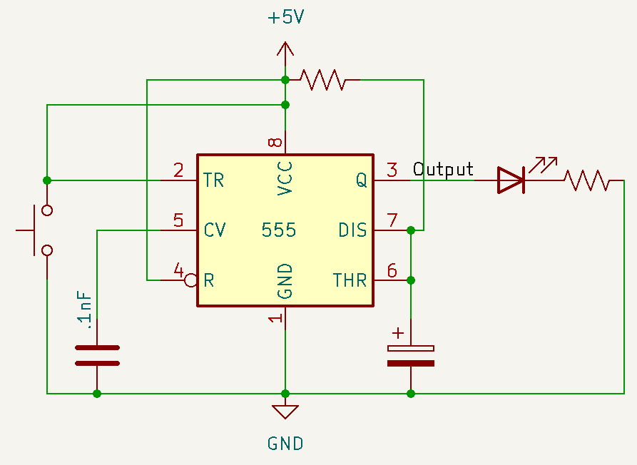
Bistable
The bistable mode, or Schmitt Trigger, functions like an SR Latch (Set-Reset Latch).
Schematic
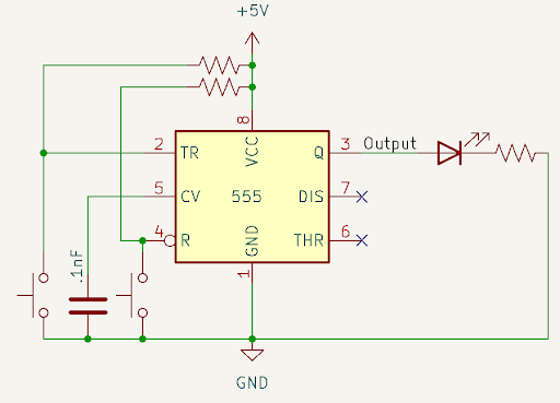
The button connected to pin 2 (trigger) is the trigger (or set, if thinking about this in SR latch logic), and this turns the output high. The timing diagram of this circuit looks like this:
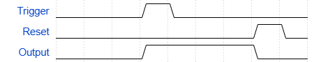
The 555 timer will hold a value until either the trigger or the reset button is pressed. This mode is used when you want a value to be stored temporarily.
Breadboard Example
Notice that the dot at the top of the 555 timer is pointing towards the bottom, indicating that pin 1 is towards the buttons. This is the same for the other circuits.
Astable
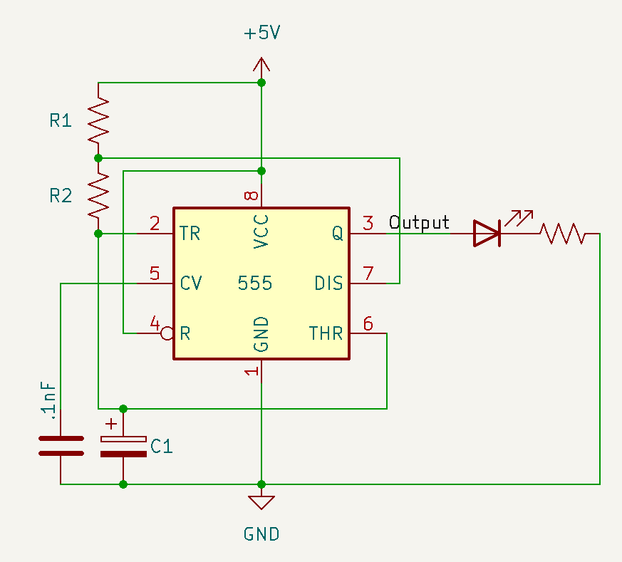
The astable mode is an oscillation between low and high. This mode is constantly alternating between a 1 and a 0, hence the name “astable.” When using a 555 timer, you can control the frequency of the oscillation with 2 resistors and a capacitor. If you want to have a precise frequency, you can calculate this frequency by using the values in ohms (Ω) of R1 and R2 and in Farads (F) for C1.
f =For example, if I had a 10KΩ resistor as R1, a 1KΩ resistor as R2, and a 47 μF capacitor as C1:
When we take a look at the timing diagram, the 555 timer has a digital output. This means the signal will go straight up and down like so:

Breadboard Example
Monostable
The name implies that this mode is stable in one state. This mode will stay in the low state until the Trigger pin on the 555 timer is pressed, which will cause the output to go high for a set amount of time.
The amount of time the output stays high is calculated by the ohms (Ω) of R1 and the Farads (F) of C1.
Tsec1.1R1C1If I had a 10KΩ resistor and a 47 μF capacitor
T = 1.1(10000)(.000047) = .517 secThis mode is especially helpful when debouncing a switch. When you press a switch, the contact points may bounce slightly, which may cause the circuit to trigger extra button presses. But with the 555 timer in monostable mode, you can use the smooth output rather than the choppy button's output.
Breadboard Example
Conclusion
The 555 timer is one of the most flexible and well-rounded components in electronics. Whether you need a simple pulse or a latch to store data, the 555 timer is a simple and reliable method. Because of its ability to operate with minimal outside components, many electronics hobbyists use it in their projects. By understanding how the 555 timer works, you'll be well on your way to designing your circuits that use these devices. If you're looking for an easy way to get started with timing circuits or want to add reliable timing control to your very own designs, the 555 timer is a tried-and-true choice that belongs in every maker's toolbox.