Beginner's Guide to Logic Gates: Types, Truth Tables, and Symbol
Computers are amazing and complex machines. But what makes computers able to compute? The answer lies in how logic gates work. Logic gates are the fundamental building blocks of digital circuits, just as cells are the building blocks of living organisms. While transistors form the physical basis of gates, logic gates define how signals are processed logically in a computer. Atoms technically make up everything, but cells are specialized for biological functions. This is similar to how transistors form logic gates, which are specialized for logical circuits.
Logic Gate Basics
Digital logic gates manipulate Boolean values using logical operations, or Boolean logic. To generalize boolean logic, any input for boolean values can either be “yes” or “no”, “true” or “false”. There is no in between like “maybe”. With logic gates and digital computers, “yes” or "true" is referred to as a “1”, and “no” or “false” is referred to as a “0”. This is called true/false logic. There are a few types of logic gates, but to start, we will focus on the NOT gate.
The NOT Gate Explained
The NOT gate takes 1 input, which, as explained earlier, can be either a “1” or a “0”. The NOT gate inverts the input:
- Inputting a 1 outputs a 0
- Inputting a 0 outputs a 1
The NOT gate itself is pretty self-explanatory, but in more complex circuits with hundreds of inputs and outputs, you will want an easier way to visualize what a circuit does. This is called a truth table.
Truth table for a NOT gate:
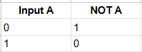
There's one input labeled “A” and one output labeled “Y”. When A equals 1, Y equals 0, and so on. This greatly simplifies explaining all the inputs and outputs of logic gates. The NOT gate also has a symbol used in schematics or logic diagrams when designing a logic circuit.

The NOT gate is symbolized by a triangle pointing to the right with a small circle at the output. The circle indicates inversion, or that the output is the opposite of the input. The input in the gate's visual is labeled A, and the output is labeled Y. These are the labels that indicate which column in the truth table corresponds to which pin on the logic gate. When we look at the inputs and outputs of the AND gate, we have double the inputs, thus doubling the different combinations able to occur on the gate.
The AND & NAND Gate Explained

The AND gate outputs true only when both inputs are true. If just one of my inputs is false, output false. An easy way to remember what the AND gate does is that it checks if both inputs A AND B are true. The AND gate symbol is also included in the image. As you can see, the second input is called B, which corresponds to the second column on the truth table. The AND gate symbol has a flat left side for the inputs and a curved right side for the output. The NAND gate is very similar to the AND gate, with one minor change.
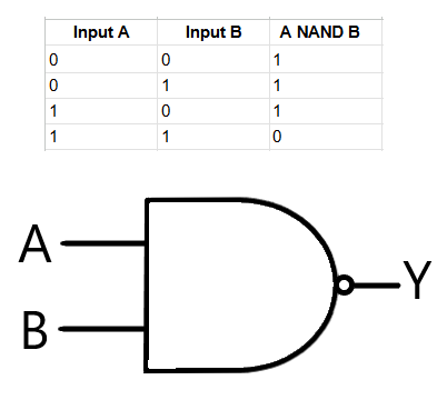
The NAND gate includes a small output circle, just like the NOT gate, indicating inversion. If you take a glance at the truth table, the outputs are exactly the opposite of the AND gates. NAND stands for “not AND,” or the inverse of the AND gate. The OR and NOR gates have the same relationship as the AND and NAND gates do.
The OR & NOR Gate Explained
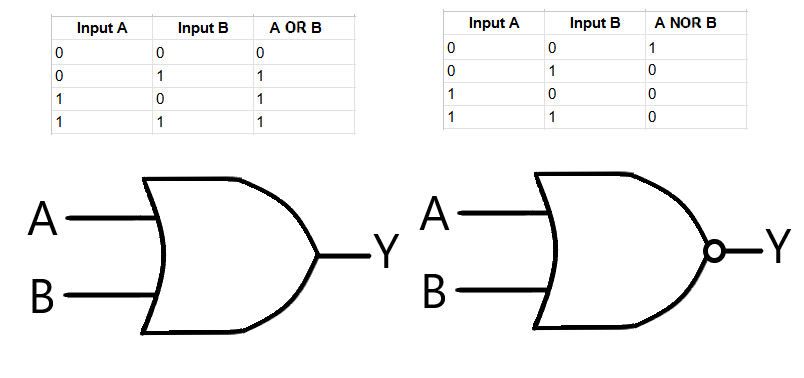
The OR gate symbol (on the left) looks similar to the AND gate, but it curves outward on the input side and comes to a point at the output. The OR gate takes two inputs, and if A or B is true, then the output is true. NOR (on the right), like NAND, means “not OR,” and its inputs are completely reversed from the OR's. The only time the NOR is true is if none of the inputs are true.
The XOR & XNOR Gates Explained

The XOR and XNOR gates resemble the OR gate symbol but with an additional curved line on the input side, distinguishing them as 'exclusive' gates. The X in XOR stands for exclusive. The XOR gates output a 1 if the two inputs are not the same and a 0 if the inputs are the same. These gates are mainly used for adding two numbers together. XOR gates are used in binary addition because they determine the sum bit without carry (15 + 8 = 23, the carry is the 2 in 23. An XOR would output the 3, the sum bit, in 23). If you're adding two bits, A and B, the sum bit is the corresponding row for A and B, and the carry-out bit is an AND operation on A and B. The logic for the lower two bits would look like the XOR's truth table.
Like the NAND and AND gates, the XNOR is "exclusive not or," and its outputs are inverted (given by the circle on the output).
Conclusion
Logic gates are essential components in digital electronics, forming the foundation for all computing devices. The device you are reading this on likely has tens of thousands of these little gates all racing at lightning-fast speeds to render this on your screen. I encourage you to learn more about logic gates and how they work. Logic gates aren't just concepts. Logic gates exist physically, and it is possible to build logic gates on your own with transistors.