Make Logic Gates on a Breadboard: Easy Transistor Projects for Beginners
Learning about transistors can greatly help when trying to understand the basic concept of logic gates and how they work. Similar to how learning the alphabet is the first step to understanding how words sound, learning how transistors work is essential to understanding how logic gates and computers work. Transistors reveal the true Boolean logic behind logic gates, as well as how voltages in a circuit produce the Boolean logic. Transistors can be a great visual way to understand logic gates. You can even build these logic gates yourself.
What is a Transistor Switch?
The most basic transistor circuit, making a switch with transistors, can have many uses. The way a transistor switch works is by allowing a small signal (like from a sensor) to control a larger load, like an LED or motor. A transistor has 3 pins:
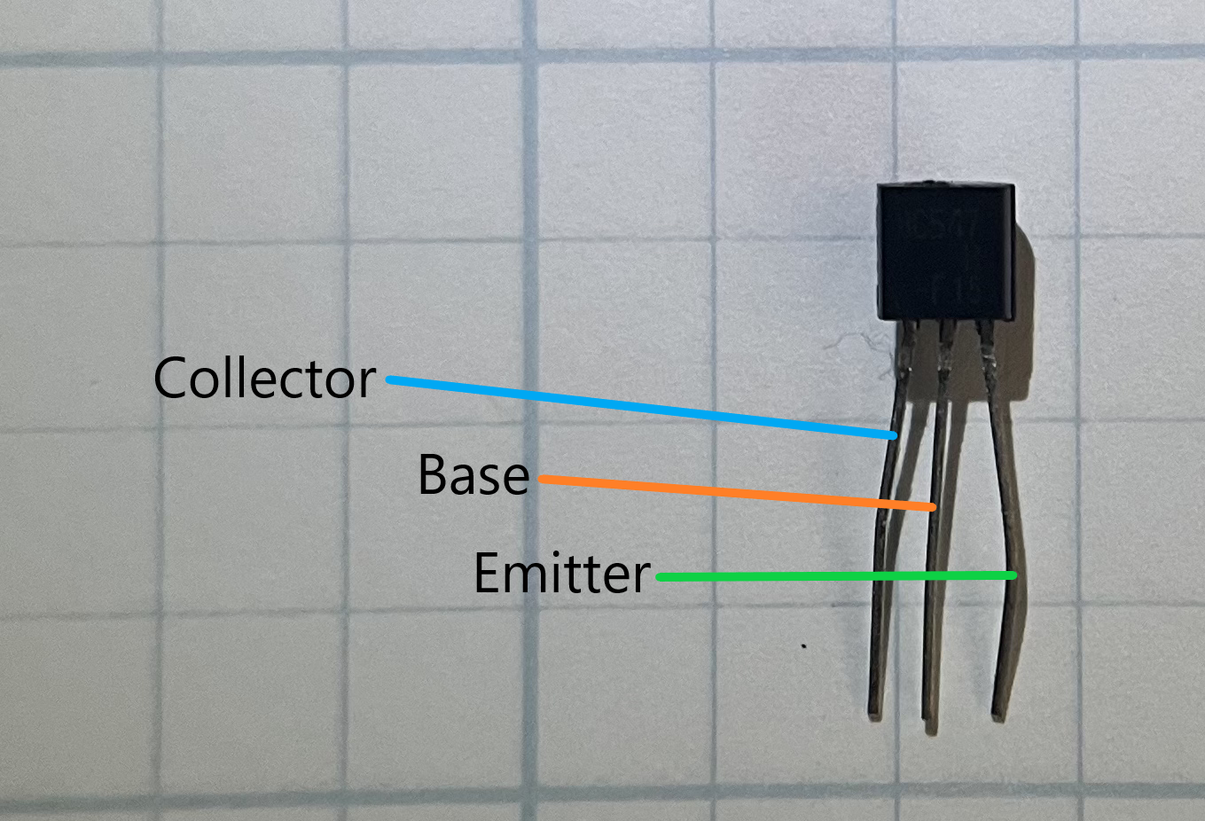
- Base - acts as a switch
- Collector - where current flows in
- Emitter - where current flows out
When a small current is present at the base, then the transistor turns to the “on” state, which allows the current present at the collector to flow to the emitter. With no current at the base, the transistor is “off” and the current from the collector is unable to flow to the emitter.
BC547 Transistor Pinout
How to Build a Simple Transistor Switch
To build a standard transistor switch, here are the steps:
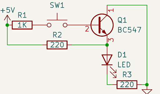
- Connect one side of a 1KΩ resistor (R1) to the base pin and the other side to a switch.
- Connect the collector to +5V.
- Connect the emitter to the positive side of an LED (with the negative side going to ground through a 220Ω resistor).
This may seem pretty confusing. To clarify, here's the schematic:

In most schematics, GND will mean ground. We can apply this circuit in real life by using a breadboard:
Building Logic Gates with Transistors
Logic gates are simply transistors connected either in series or parallel. There can be any number of transistors in a logic gate, depending on how many inputs you want on your gate. Below are the most basic logic gates.
How to Build an NOT Gate With Transistors
To build a NOT gate, you need 1 transistor. This gate outputs the inverse of the input. To make this gate, we can start by using the transistor switch we made previously. Then, by reversing the way the LED is connected and adding a 220-ohm resistor from 5V to the emitter, we create an inverter.
Schematic
Breadboard Circuit
How to Build an AND Gate With Transistors
Schematic
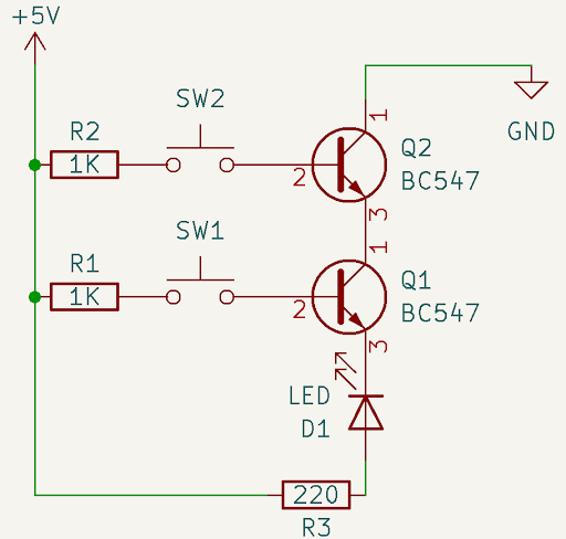
This schematic shows how the AND gate is made. In order for the 5V to get to ground, both transistors must be on. When they are, the current can pass through them and the LED, turning the LED on.
Breadboard Circuit
As you can see, the LED lights up only when both inputs are high.
How to Build an OR Gate With Transistors
Schematic
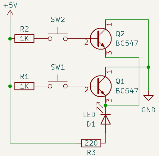
This circuit features two transistors wired to an LED in parallel. This way, if either of the transistors is active, the LED will light up, creating an OR gate.
Breadboard Circuit
If either input goes high, the LED lights up.
The NAND and NOR Gates
These gates are very similar to their inverses, the AND and OR gates. To make these gates, you would simply need to take the output of the AND or OR gate and feed it into a NOT gate to generate your NAND or NOR gate.
Conclusion
Understanding transistors is a foundational skill for anyone interested in electronics or computer systems. By learning how to build simple circuits like transistor switches and logic gates, you gain insight into how complex digital systems are constructed from basic components. These small building blocks power everything from calculators to smartphones. As you continue experimenting with transistors and logic gates, you'll be well on your way to mastering the language of modern electronics. A great next step is to explore deeper into computer architecture.
People also ask
Special Thanks to Jameco
This is a little thank you to jameco.com for supplying me with all my electronic needs for projects like this one. I get most of my parts through this website, and they have yet to fail me in getting me my parts quickly, reliably, and easily. I would recommend using this site to satisfy all your electronic projects' needs, as they are honest and trustworthy.